BLOG CATEGORIES

Mustang

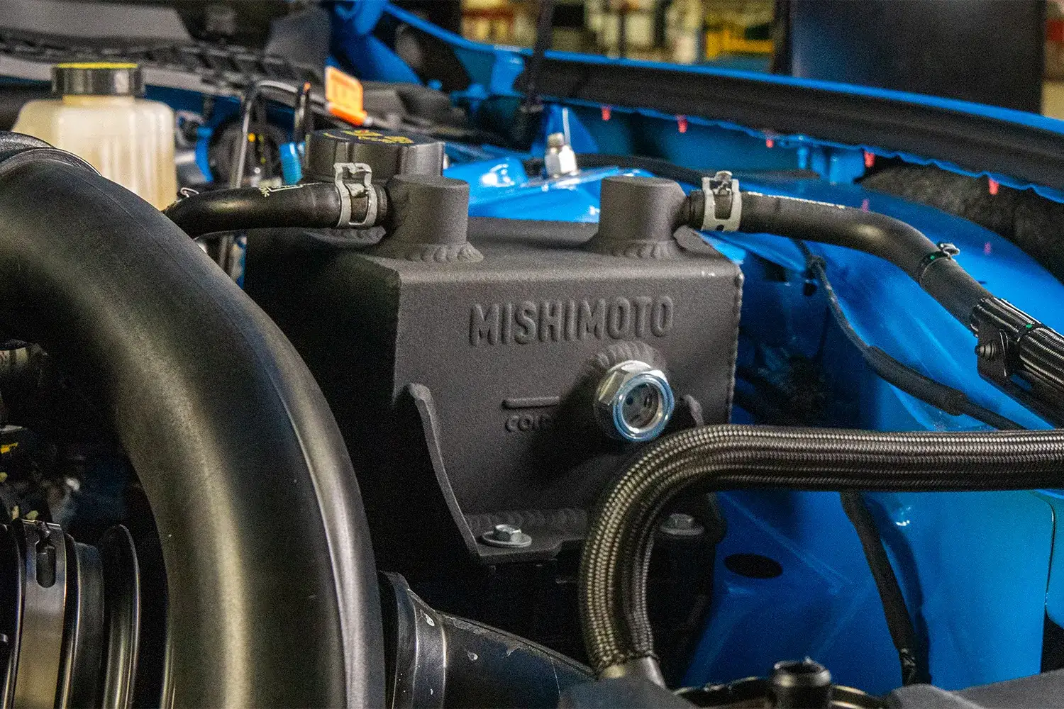
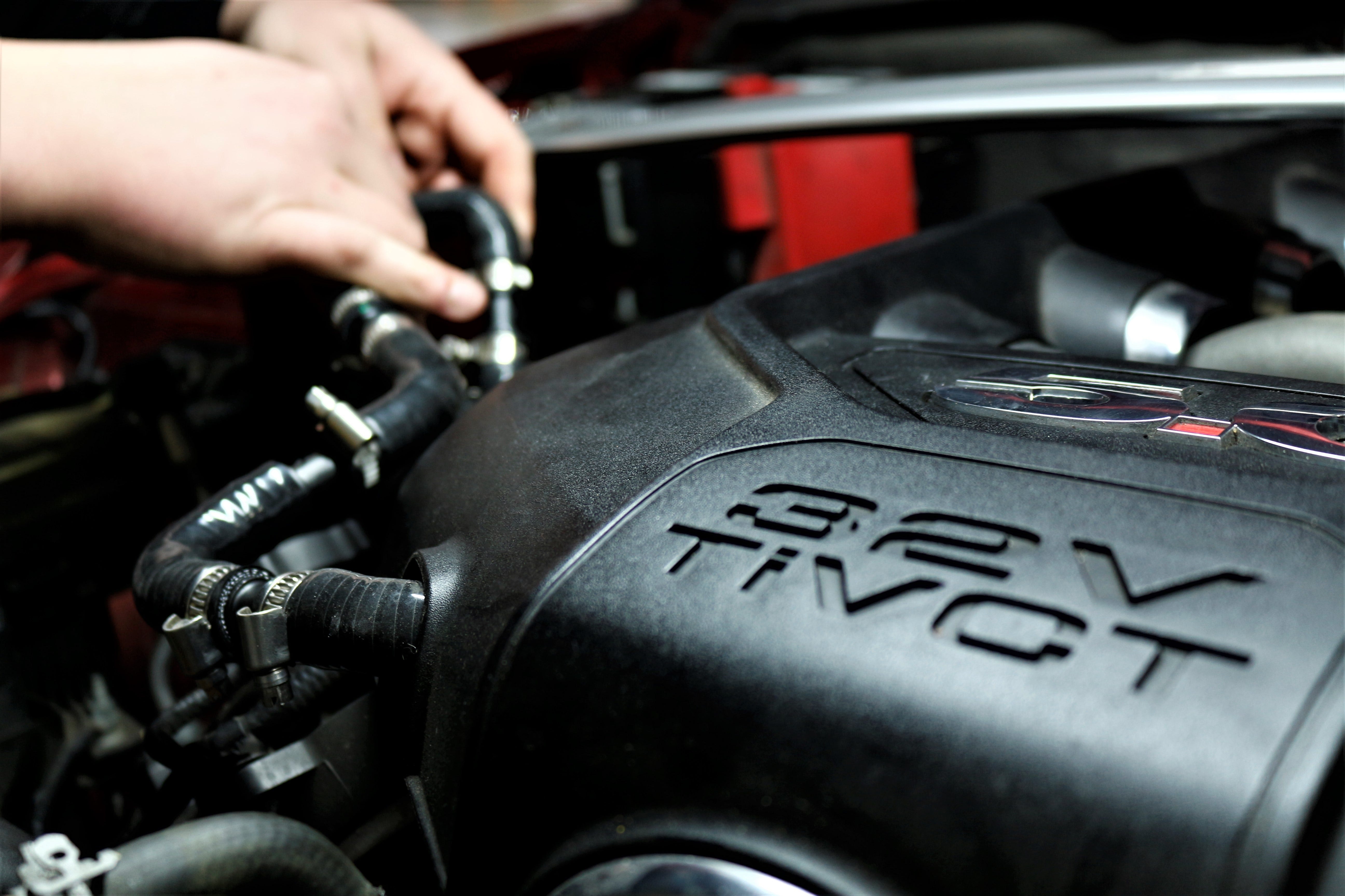
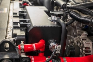
  1. Image of the Mishimoto Aluminum Coolant Expansion Tank installed in the engine bay of a 2024+ Ford Mustang EcoBoost

    Cool & Collected – Aluminum Coolant Expansion Tank for the 2024+ Ford Mustang

    Every owner of a performance vehicle knows the importance of keeping their car running cool, but not everyone knows where to start when it comes to upgrading their cooling system. For owners of the 2024+ Ford Mustang looking to take the next step in performance and reliability for their car’s cooling system, it’s best to start with the basics—the coolant expansion tank.

    The stock coolant expansion tank on the 2024+ Ford Mustang leaves a lot to be desired. The plastic construction isn’t just an eyesore, it’s not designed to stand the test of time. After repeated heat cycles the plastic yellows and becomes brittle, leading to a higher risk of cracking and coolant leakage. This risk only increases when the vehicle is driven hard, such as fast laps at the track or hard pulls on the dragstrip.
    Continue Reading »
  2. Road Test Results – Baffled Oil Catch Can for 2024+ Mustang V8

    Road Test Results – Baffled Oil Catch Can for 2024+ Mustang V8

    We’re entering the fourteenth year of production for Ford’s 5.0L Coyote V8 engine, and in that time the Coyote has made a name for itself. It’s a powerful, throaty engine that’s been in the Mustang GT since the 2011 model year. Since its inception, the folks at Ford have managed to squeeze an extra 68 horsepower out of the Coyote with the new 2024 Mustang GT boasting 480 horsepower. Despite these gains, one issue the Coyote has had for years still persists—excessive blow-by.

    What is Blow-by?

    Continue Reading »
  3. Stranger Danger - Baffled Oil Catch Can R&D, Part 3: Finishing Touches

    Stranger Danger - Baffled Oil Catch Can R&D, Part 3: Finishing Touches

    The prototype has been on our loaner GT for the past few months, working as it should and catching a nice amount of blow-by. The previous updates, covered how we used innovative tech to design and create the bracket, and the planned routing for the lines. Significant progress has been made since then, as the designs have taken a cleaner physical form.

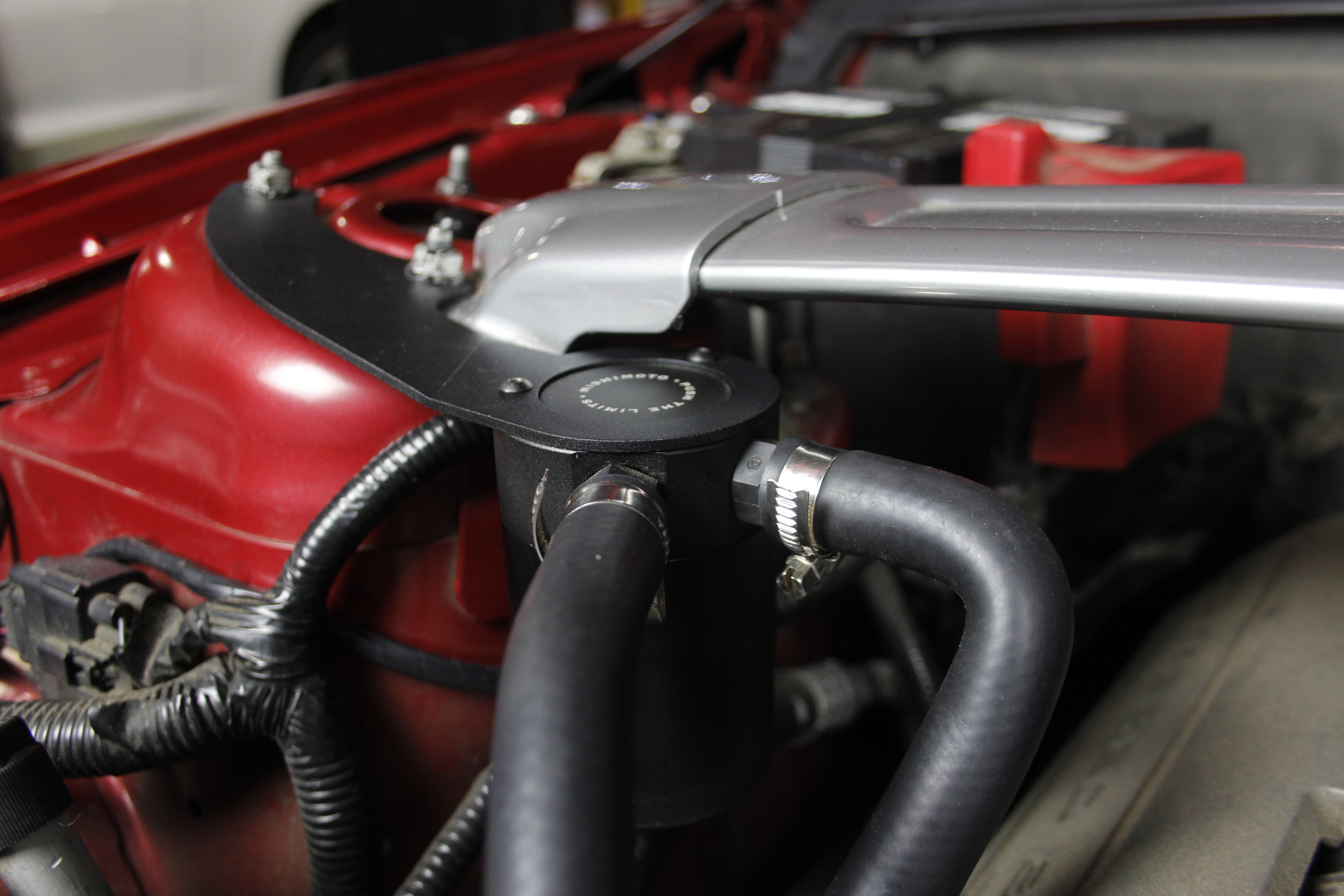
    Side shot of the completed kit
    Side shot of the completed kit

    Our sample production kit arrived at our R&D headquarters and it couldn't have fit any better. Everything was spot on and the installation was easy. You can see in the above image that we've cleaned up the catch can lines with properly routed hoses. The line material is rubber based, retaining a clean, OEM look.

    To keep this

    Continue Reading »
  4. Stranger Danger - Baffled Oil Catch Can R&D, Part 2: A Canned 'Stang

    Stranger Danger - Baffled Oil Catch Can R&D, Part 2: A Canned 'Stang

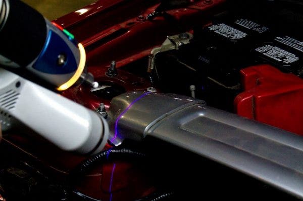
    Our engineer has advanced engineering tools at his disposal. Arguably, one of the coolest in our facility's arsenal is our scanning device. This high-tech piece of equipment allows our engineer to scan anything in 3D space into a computer file. The file is then uploaded to a computer so the engineer can design whatever they want within the 3D space they scanned. The fine-tuned hands-on engineering element is still there, it's just done a lot faster and just as accurate with this machine.  We call this contraption the Faro Design ScanArm and we have a full, detailed writeup on how it works. Cool technology aside, let's get into the design of this catch can kit.

    The scan-arm at work!
    The scan-arm at work!

    Continue Reading »
  5. Stranger Danger - Baffled Oil Catch Can R&D, Part 1 - Design Plans

    Stranger Danger - Baffled Oil Catch Can R&D, Part 1 - Design Plans

    Our engineers at Mishimoto are no strangers to the dangers of oil blow by. We have well-documented evidence that this is still a common threat to most modern direct injected vehicles. For those of you that don't know, blow-by is a byproduct of compression and combustion. Blow-by is created when oil and fuel vapors push past the piston rings and into the crankcase during compression. To keep the crankcase depressurized from this oil and fuel, there needs to be some sort of venting. This is accomplished by routing this blow-by through the intake tract and right back into the cylinder to be burned during combustion.

    Even though this particular engine uses port injection, which sprays fuel directly onto the valves, the problem still lies within the venting process. By rerouting blow-by through the intake tract, there is a potential for accumulating carbon deposits on your valves in addition to a nice thin coating of oil along the inside walls of your intake (and turbo if applicable). The

    Continue Reading »
  6. Keep your Cool- Transmission Cooler R&D, Part 3: Test Results

    Keep your Cool- Transmission Cooler R&D, Part 3: Test Results

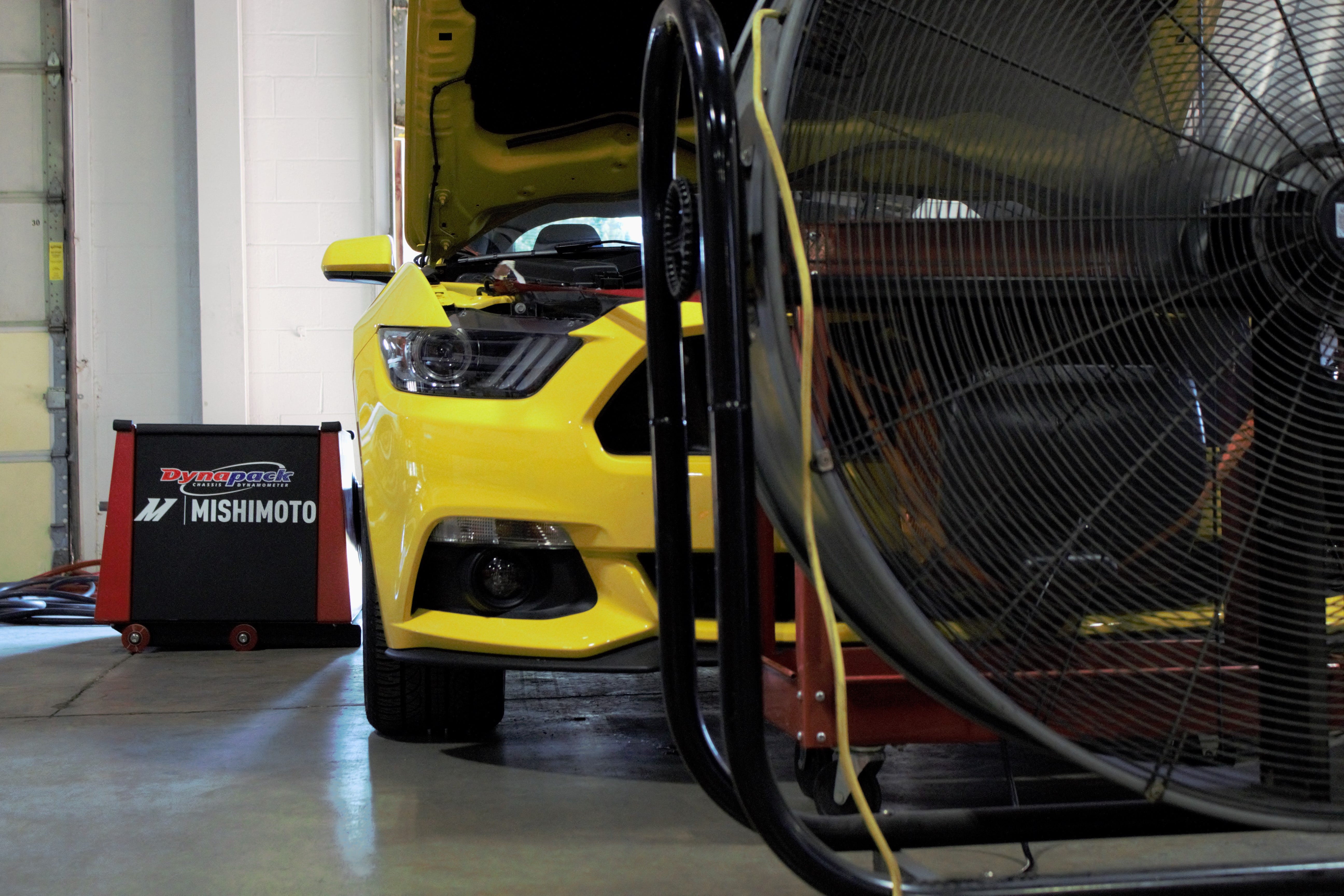
    The yellow GT is back in our R&D facility to show us a thing or two about testing trans coolers. Upon the GT's arrival, we wasted no time getting the pony car saddled with our testing rig.

    Mustang GT on the dyno for transmission cooler testing
    Mustang GT on the dyno for transmission cooler testing

    Mustang GT on the dyno for transmission cooler testing
    Mustang GT on the dyno for transmission cooler testing

    We couldn't have asked for a better day for our Mustang transmission cooler testing. We began testing on

    Continue Reading »
  7. Keep your Cool- Transmission Cooler R&D, Part 2: Prototype Fitment

    Keep your Cool- Transmission Cooler R&D, Part 2: Prototype Fitment

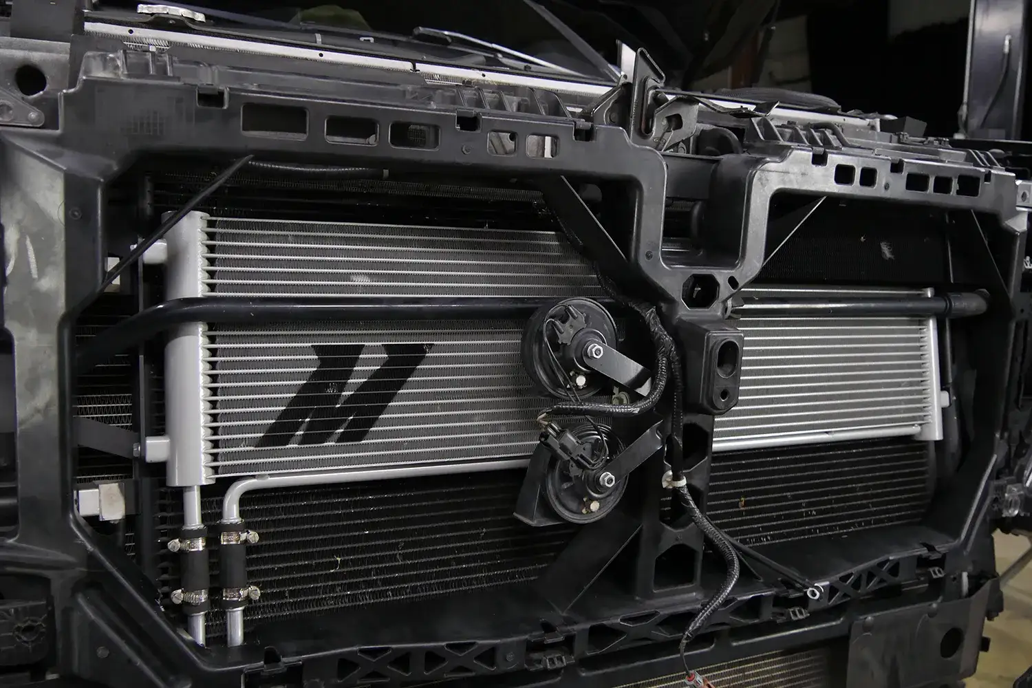
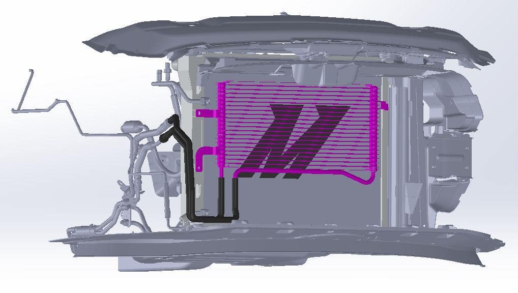
    In our last post, we took a look at the stock Mustang automatic transmission cooler and our plans to make it even better. We designed the cooler in Solidworks, based off the measurements obtained from both the GT and the stock cooler. We will be doing our R&D with this bold yellow GT, but based on our research, this cooler will fit all models of S550 Mustang including the EcoBoost and V6. But enough about fitments, the prototype is complete! It is time to see how well our digital design translated into a real-life prototype.

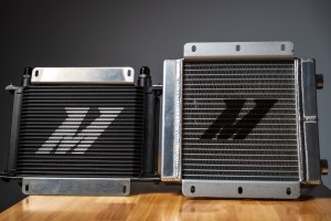
    Mishimoto Mustang trans cooler
    Mishimoto Mustang trans cooler

    So far the trans cooler is looking good. It is much larger than the stock cooler, 50% larger to be exact. The stock cooler comes in at 10 rows, where the

    Continue Reading »
  8. Keep your Cool - Transmission Cooler R&D, Part 1: Prototype Design

    Keep your Cool - Transmission Cooler R&D, Part 1: Prototype Design

    Over the past year we have been getting acquainted with our Mustang GT, and in the process we've developed an entire line of cooling products for it. In the spirit of staying cool, we are on to our next project, the Mustang GT Automatic Transmission Cooler.

    Donor vehicle for Mustang GT trans cooler testing
    Donor vehicle for Mustang GT trans cooler testing

    Heat is generally the enemy of an automatic transmission. In fact, the Ford factory service manual notes that when the GT's computer senses the transmission overheating, it will limit RPMs until the temperature returns to a normal range. There is nothing worse than a track day ending early due to high temps of any kind, including in the transmission. Whether you are taking your GT to the track

    Continue Reading »
  9. Stiffen Your 'Stang! 2015 Mustang Strut Tower Brace R&D, Part 5: Final Testing Rig and Results

    Stiffen Your 'Stang! 2015 Mustang Strut Tower Brace R&D, Part 5: Final Testing Rig and Results

    What a unique and exciting project this has been! We don't want to simply develop neat products; we want to understand how and why they function. This is why our team has been working to develop test protocols for our S550 Mustang strut tower brace evaluations. This segment shows our final testing process and the very surprising results.

    Final Testing Rig

    After experimenting with a setup designed to record pressure, we noticed that measuring travel distance between the two strut towers would provide identical results if we used a much more adaptable testing device.

    Our team acquired a few linear-displacement gauges to modify our strut brace for testing. We started by hacking apart one of our prototype bars.

    2015 Mustang parts testing
    Continue Reading »
  10. Stiffen Your 'Stang! 2015 Mustang Strut Tower Brace R&D, Part 4: Testing Rig Fabrication Continued

    Stiffen Your 'Stang! 2015 Mustang Strut Tower Brace R&D, Part 4: Testing Rig Fabrication Continued

    Last time we wrapped up our first attempt at creating an accurate gauge for measuring strut tower flex. Our initial tests showed some inconsistencies, which have been attributed to the method by which we mounted our gauge.

    These inconsistencies occurred most likely because of the difference in materials. Our strut bar is steel, whereas the gauge assembly is aluminum. Welding these materials together is not possible, so we used alternate methods.

    We need to eliminate any adverse variables for this test. Measurements of movement are small, so even a seemingly insignificant issue could cause skewed data. We decided to work up a full aluminum prototype modeled after our first design.

    All-Aluminum Strut Bar Testing Prototype

    In addition to new machining tools, we have a new high-pressure Waterjet cutter here at Mishimoto. We decided to flex its muscles a bit and use it to cut out our strut bar brackets. These were then welded to the bar itself

    Continue Reading »
Page