Cool Air for the EcoBoost. F-150 Intercooler R&D, Part 2: Initial Design Work
After taking a brief look at the factory cooler and components, we needed to begin the design for our counterpart. This will involve the use of both modern and conventional tools to ensure that our prototype meets all our requirements.
Factory Intercooler Features
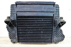
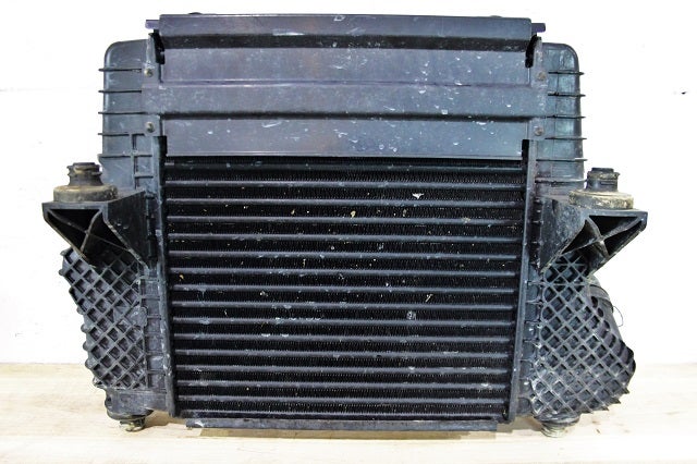
Factory F150 intercooler
The factory intercooler pulled from our test vehicle came with the upper shroud that Ford had added to help prevent condensation issues. It also included a couple mounting pegs which use grommets for isolation.
Factory F150 intercooler
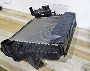
The rear of the cooler reveals two inlets, one outlet, and the electronic bypass valve (BPV) unit found on the 2013 and 2014 models.
Factory F150 intercooler
We removed the BPV unit and inspected the connection point. We would need to replicate this with our design to provide bolt-on fitment.
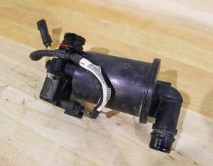
Factory F150 intercooler bypass valve
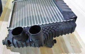
On this cooler, the two inlets are a simple push-on and clamp-style connection. The outlet is a quick-disconnect. We will be emulating this connection in our design, so obtaining precise measurements is important.
After inspecting the quick-connect, we found it to be similar, though not identical, to that of the Ford 6.7L Powerstroke CAC connection. We will need to model a new quick-connect for this cooler.
Factory Cooler Dimensions
We need our intercooler to bolt up to the vehicle in a manner similar to the factory piece. We don't want our customers cutting, drilling, or grinding anything if it can be avoided.
We set the stock cooler on our CMM (coordinate measuring machine) to capture mounting points, sizing, and feature dimensions.
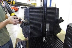
Factory F150 intercooler on CMM table

Factory F150 EcoBoost intercooler on CMM table
Prototype Core Sizing
We also needed to get an idea of the core size for our prototype, which requires some test fitting. For this process, we often use hardened foam to put together a general shape or size. This foam material is easy to cut and makes the process relatively quick.
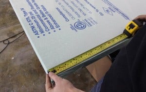
Foam for F150 EcoBoost Intercooler mockup
We completed our basic shape after making several cuts.
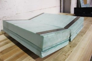
Prototype F150 EcoBoost intercooler core
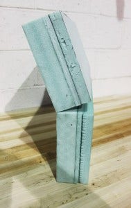
Prototype F150 EcoBoost intercooler core
The metal strapping was added to provide some additional rigidity for our test fit. Once the shape was refined, we placed the prototype in the truck to check fitment.
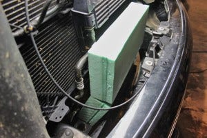
Prototype F150 EcoBoost intercooler core installed
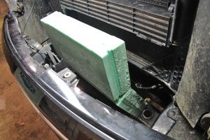
Prototype F150 EcoBoost intercooler core installed
As you can see, we've opted to locate the cooler in the same position as the factory unit to take advantage of airflow from the lower duct. Moving the cooler to the upper portion of the grille would restrict airflow to the radiator and transmission coolers. Such a restriction would have an impact on efficiency in certain driving situations.
We are planning to increase the core volume significantly. This, along with a strategically designed core, should result in some nice improvements in intake temperature.
Coming up - 3D Models
Our engineering team is putting together some 3D models of our initial design so we can start creating a functional prototype (or two) for testing purposes. Check back soon for a neat update!
Thanks for reading!
-John
