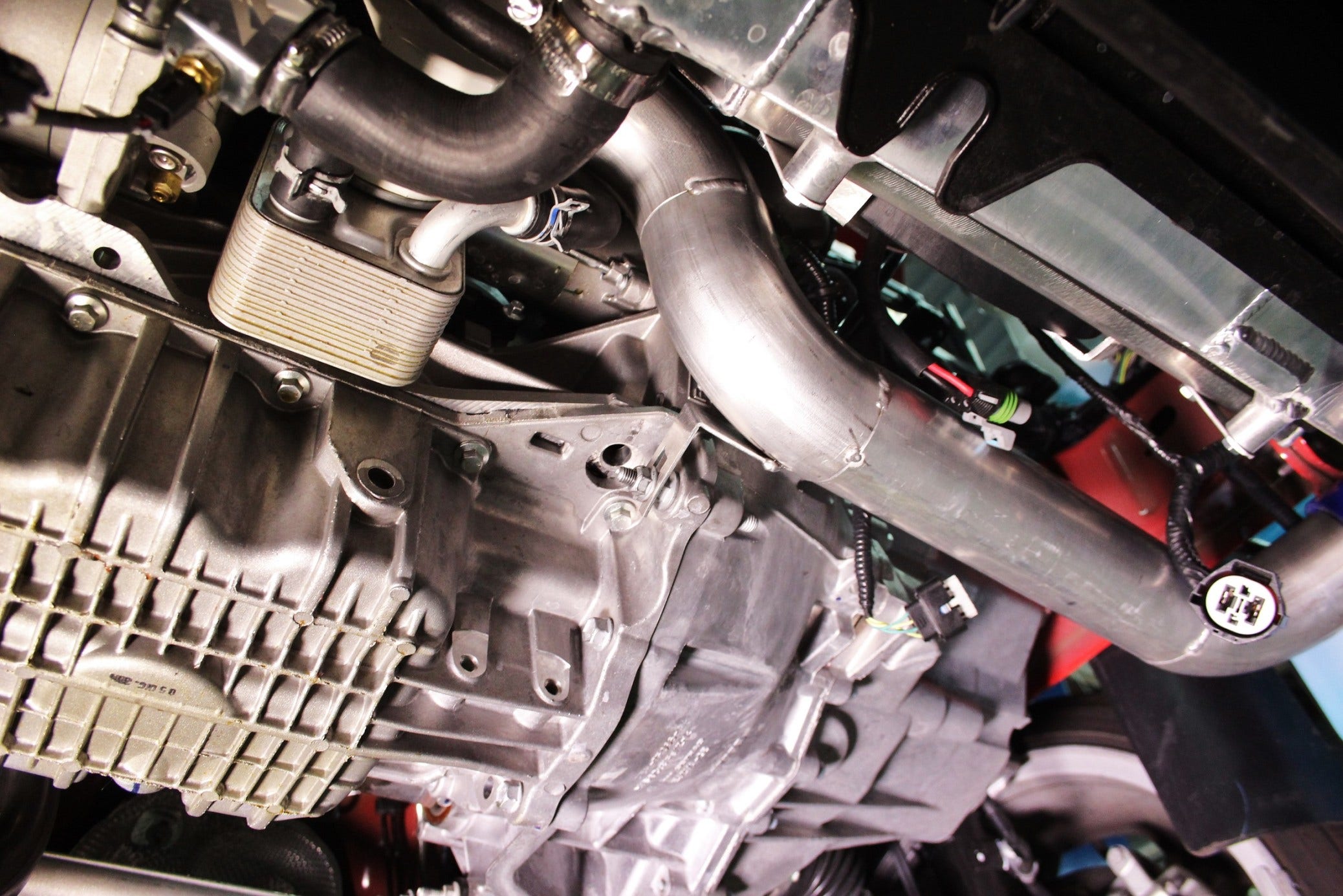
Pipe Down. Mishimoto Fiesta ST Charge Pipe R&D, Part 2: Cold-Side Prototype Fabrication
Stock Cold-Side Features
We had it pretty easy during the design phase of our hot-side intercooler pipe. A simple design with relatively common features, not overly complicated. The cold-side is a different story.
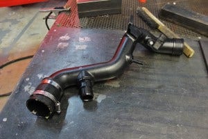
Stock Fiesta ST charge pipe
As you can see, this pipe features a few complex pieces and also follows an unusual path. On the right side at the top of this image, you can see the end of the pipe that mates to the intercooler coupler and hose. This portion of the pipe also houses a pressure sensor, a mounting bracket, and a vacuum-line port.
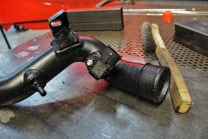
Stock Fiesta ST charge pipe
Each of these features will be replicated in our design, and in addition we will be increasing the piping size to 2.5" throughout. The stock piping features ends with 2.5" diameters; however, most of the inner portion of the pipe measures around 2" in diameter. The stock throttle-body diameter measures in at 2.25", so we will be using a reducing coupler at this connection point.
The other end of the pipe features the port for the sound symposer.

Stock Fiesta ST charge pipe
Here's one more look at this stock intercooler pipe installed.

Stock Fiesta ST charge pipe installed
Pipe Route Fabrication
Before handling the unique sensor connection, mounting points, and BPV fitting, we started to fabricate the piping portion of the design. Compared to the stock unit, our pipe would feature a larger internal diameter for achieving improved flow. Because of this increased diameter, we needed to ensure that our component would have appropriate clearance within the confined space between the engine and cooling fan.
Check out some of our handiwork!

Fabricating Fiesta ST performance parts

Fabricating Fiesta ST performance parts
After finalizing our projected route, we mocked-up the location of the necessary mounting components, the sensor port, the symposer port, and the vacuum port.
Check out a couple shots of our mock-up unit.

Mishimoto fabricated Fiesta ST performance parts

Mishimoto cold-side pipe, initial prototype
Keep in mind that this is a rough prototype. The primary function of this piece is to locate each feature so we can input this information into our upcoming 3D model. This is in no way designed to be a functional or pretty piece.

Mishimoto fabricated Fiesta ST performance parts
The image above shows the location of our symposer port, vacuum port, and the mounting bracket for the pipe.
The next shot shows our location for the pipe-mounted pressure sensor.

Mishimoto cold-side pipe, initial prototype
Coming Up!
After constructing our two prototype pipes, we need to export our data into a 3D model in Solidworks. Once complete, we can produce functional prototypes and conduct some dyno testing.
Next time we will have our 3D models complete and ready to display for your viewing pleasure!
Thanks for reading!
-John
