Mishimoto 2015 Subaru WRX Direct-Fit Baffled Oil Catch Can System, Part 2: Product Prototyping
Interested in purchasing our WRX catch can kit? Check out more details on our product page linked below!
Subaru WRX Baffled Oil Catch Can System
Time to start designing brackets! After a quick recap of the project goals, our creative engineering team began brainstorming. First, they selected a location for the catch can on the PCV valve side. It would need body mounting points for the can bracket, and preferably a short route for the hose so as not to complicate the engine bay. Our goal is a clean installation that appears stock-like, not a medusa of hoses routed about the engine bay.
The PCV valve on the 2015 WRX is located under the intercooler toward the rear of the engine block. You can see it in the image below, taken during a later stage of development of this kit.
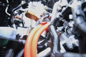
2015 Subaru WRX PCV valve
We also needed to consider the differences between the RHD and LHD vehicles. In our US spec LHD model, both the brake booster and master cylinder are located on the left side of the engine bay. In the RHD model, they are located on the opposite side. To avoid developing a kit for each setup, we would attempt to keep this bracket toward the front of the engine bay.
Eventually we found an ideal location between the PCV valve and the intake, near the ABS block. Check out a few shots of our initial mock-up design.
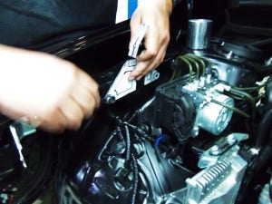
Catch can bracket mock-up
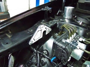
Catch can bracket mock-up
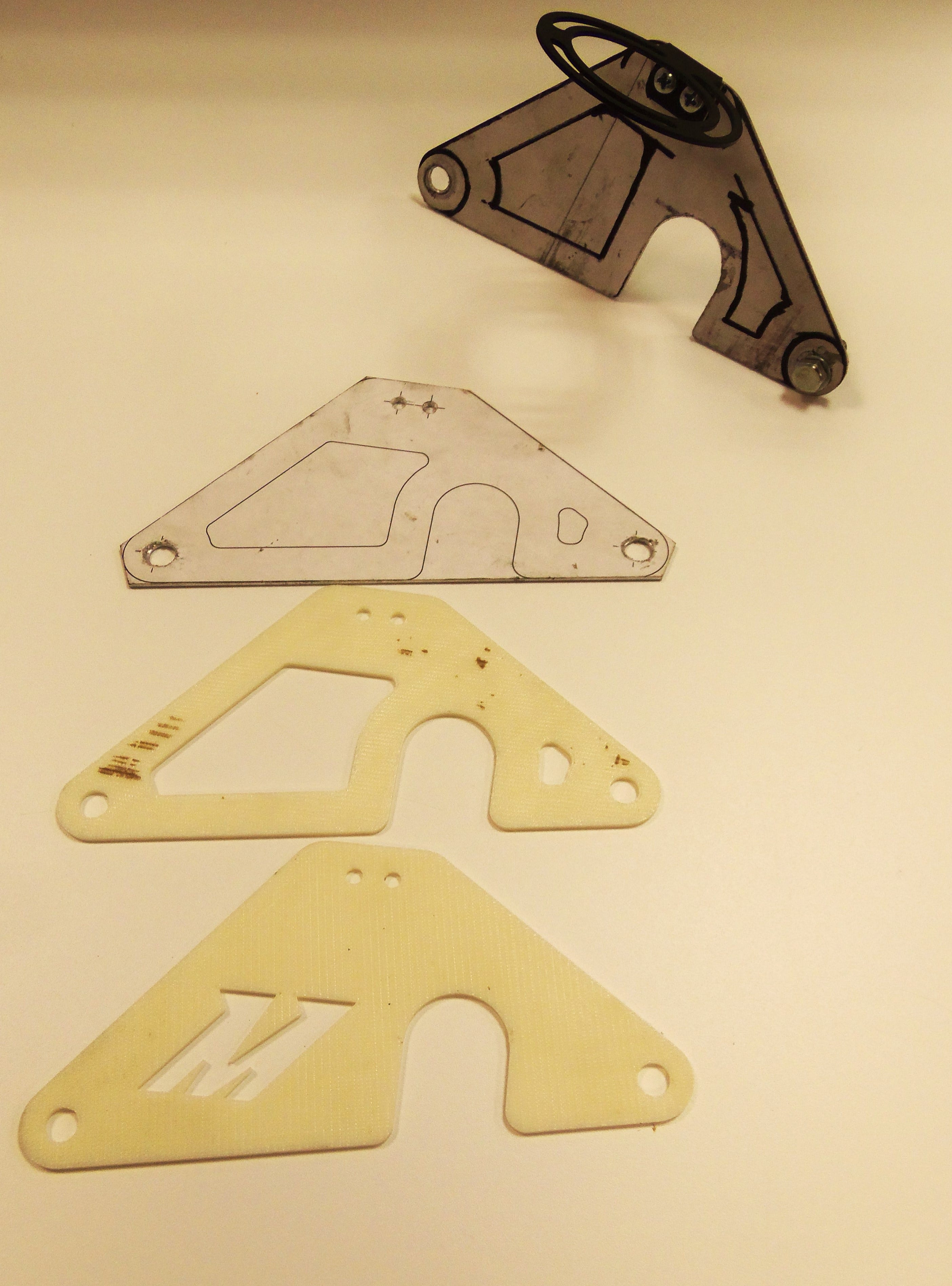
Once the primary bracket was bolted into position, we attached the baffled catch-can bracket to this piece. These brackets were designed based on engine bay dimensions and fabricated from a sheet of steel. See the attached brackets below!
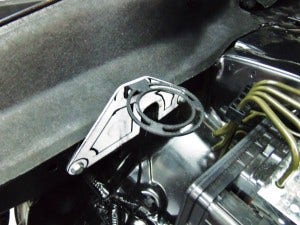
Catch can kit bracket mock-up
Then we attached the catch can to ensure proper clearance for servicing the can when fluid collects in it.
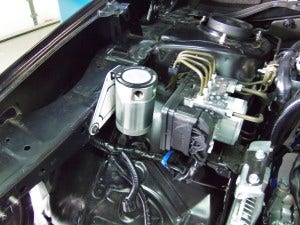
Catch can kit bracket mock-up
Once we were satisfied with the catch can on the PCV side, we moved to the other side of the system to address the CCV system. Previous-generation WRX models with the EJ engines utilized a port on each valve cover for the crankcase ventilation. That setup would have necessitated either a three-port catch can or dual two-port units. On the new FA20DIT, a single CCV port is used and can be found on the driver's side cylinder head just behind the AC compressor. Check out the port in the image below!
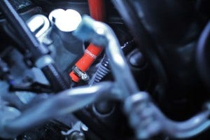
CCV port location
This line then runs across the engine bay and down into the compressor inlet pipe, as you can see below.
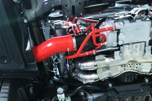
Turbocharger compressor inlet hose
Once we knew how the lines would be routed, we needed to select a bracket location and then mock-up a prototype. Again, we would be targeting the front area of the engine bay to reduce the chance of fitment concerns with RHD models. We found an optimal location right next to the battery. Check out the installed bracket and catch can with some prototype lines.
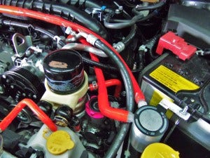
Driver's side prototype bracket
After our initial prototypes were fabricated, we put our 3D printer to work and began printing the brackets as well as a few of the catch can components.
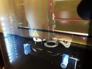
3D printing of prototype brackets
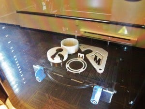
3D-printed prototype brackets
Once completed, we test fit the modeled brackets on the vehicle to verify proper fitment. Take a look at the stages of bracket design in the following images!
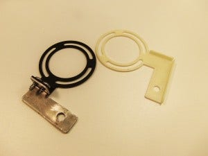
Prototype brackets
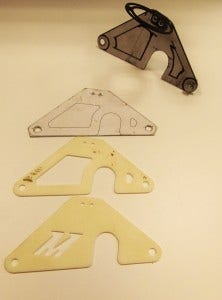
Prototype brackets
Now that the brackets were completed, we needed to design our custom hoses for this kit and ensure that all components worked together correctly. Our team would be designing these hoses in silicone to provide improved durability and resistance to heat and the fuel/oil particles flowing through them. These particles accelerate wear on rubber components, and our silicone lines would be more resilient.
Check back next time for a look at our completed kit!
