2013+ Subaru BRZ / Scion FR-S Performance Cold-Air Intake, Part 2: Initial Product Design
Interested in purchasing our BRZ intake? Check out our product page for more information!
Mishimoto Subaru BRZ / Scion FR-S Performance Cold-Air Intake
With a general idea of our plans for this product, we set about removing all the necessary components so we could begin fabrication. Steve, one of our bright engineers, would be taking the helm for this particular project, with others lending a hand throughout the process when needed.
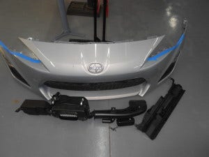
FR-S components removed
Our first task was to fabricate the main portion of the intake pipe. We would be using a separate piece to house the MAF and air straightener. This particular pipe routes air from the front bumper area into the engine compartment. We needed to decide on a pipe size and route that would provide the least restriction, greatest airflow, and most effective A/F ratios. Take a look!
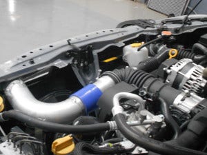
Mishimoto intake pipe fabrication
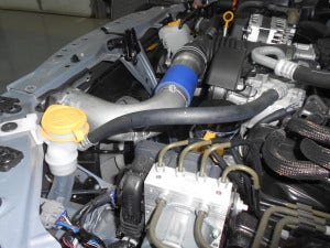
Mishimoto intake pipe fabrication
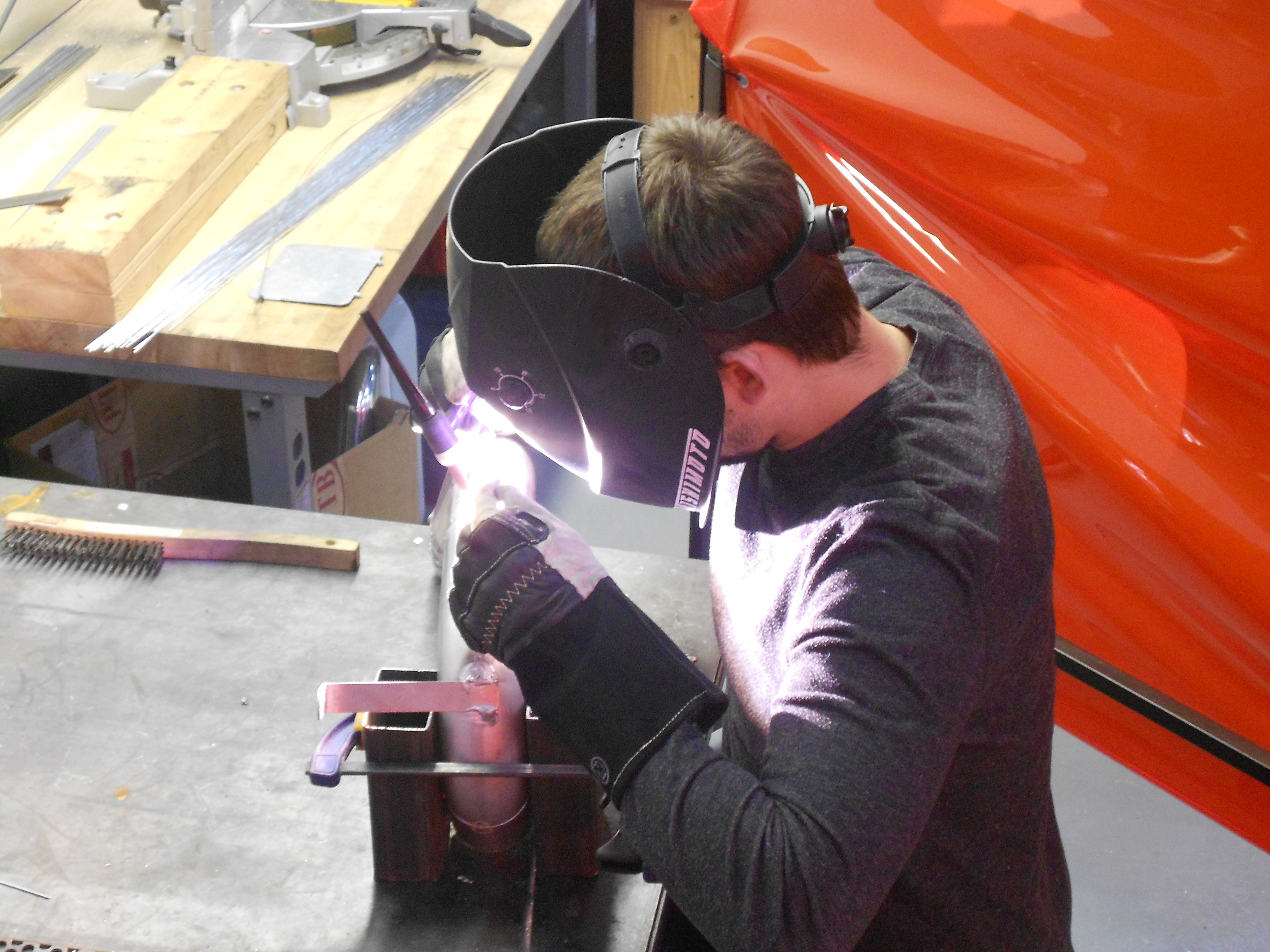
So now you have a good idea of our plan of attack. This design has many immediately apparent benefits. For one, it really cleans up the appearance of the engine bay. Also, the filter is located outside of engine bay, resulting in cooler air induction. Check out a few shots from the process of putting this pipe together.
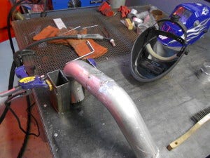
Mishimoto intake pipe fabrication

Steve handling the TIG work
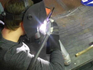
Tacking together our initial prototype
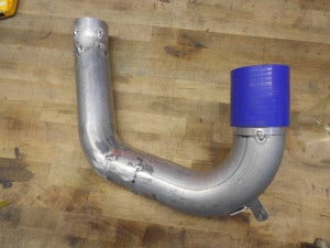
Completed intake pipe prototype
With this component complete for now, we will move on to the MAF housing, which requires even greater precision. The MAF housing is a unique piece and necessitates some expertise. The stock MAF is designed to read air volume, which is based on the diameter of the pipe where it is installed. Adjusting this diameter can result in some very interesting effects on A/F ratios, as we found when designing our previous intake kit. An easy way to lean the mixture slightly is to increase the pipe diameter where the MAF is located. When properly controlled and tested, this can provide consistent performance gains. With some experience in our back pockets, several iterations of this MAF housing were designed so we could evaluate the overall effects on performance and A/F ratios. This job would be as much a case study as it would be product development. We were pretty excited to see how minute differences would affect these aspects of testing. Check out the fabrication process!
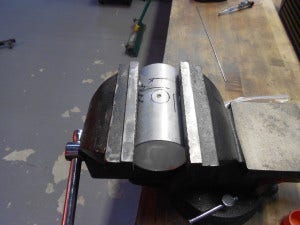
MAF housing fabrication
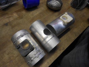
MAF housing fabrication
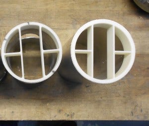
Air straightener
You will notice that we utilize several 3D-printed components during our development process. This particular housing is using two, one for the MAF mount and the other for the air straightener. The process of creating these components in Solidworks and then printing them simplifies and significantly expedites our development process. With this technology we can build and test prototypes much quicker, which results in a shorter period of time for getting these products to market. Let's all raise our glasses for technology!
Although it may seem like a small component, the air straightener makes quite an impact on the function of this product. By creating laminar flow we can provide smoother power delivery and consistent readings of airflow.
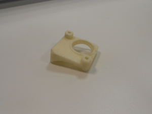
MAF housing mount
We can churn these units out in hours instead of the time it would take to have them CNC-machined. The final product will of course be machined from billet aluminum and welded to the pipe, but for our testing, we would be using a strong adhesive to attach these components. Check out the images below of the fully installed prototype, ready to go!
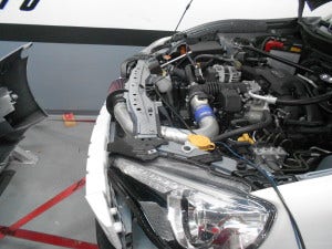
Mishimoto prototype intake fully installed
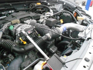
Mishimoto prototype intake fully installed
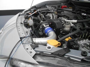
Mishimoto prototype intake fully installed
A few things to note! The device you see on the passenger side of the upper radiator support is capturing rpm data from the harmonic balancer for our Dyno testing. This intake is ready for some initial testing utilizing our different sizes of MAF housings. Check back next time when we collect our initial data and decide on a final design for moving forward.
Thanks!
