2008+ Subaru WRX/STI Performance Air Intake Part 3: Prototype Testing
Interested in purchasing our WRX/STi intake? Check out more details on our product page linked below!
Subaru WRX/STi Performance Cold-Air Intake
With our initial designs complete and fully assembled, the engineers were ready for testing. We strapped our STI to the dyno and began making some initial pulls with the car completely stock and using the OEM intake. We were averaging upper 250s to lower 260s at the wheels, which was what we expected from this car. After having some fun we removed the factory intake system, including the airbox, air induction tube, and MAF housing. We bolted on our first design and made a few pulls. We found that the air/fuel ratio (AFR) was a bit on the lean side for our tastes, so after a few runs we decided to call it quits for the day and reevaluate this design. Bolting on the second design provided slightly improved AFRs, but they were still at a point where we were a bit uncomfortable. This was our main concern, as the vehicle seemed to be putting out pretty significant gains at 20+ hp over the stock unit. The OEM Subaru MAF is programmed to the cross-sectional area of the intake tube to which it is mounted. With this in mind, our design featured OEM-exact sizing. The higher AFR is due to increased airflow that results from restriction elimination and improved airflow from the high-flow filter.
The factory tune with the OEM airbox runs quite rich in boost, most likely for safety. Many would agree that leaning this mixture slightly is a great way to gain additional power without compromising the integrity of the engine.
Our goal was to keep the AFR below 12:1 under boost, which is deemed to be the safe zone for most turbocharged vehicles. Any AFR above 12:1 is a more aggressive tune for increased power, and anything above 13:1 becomes dangerous with a high probability for predetonation.
We needed to evaluate our designs, so we went back to the drawing board to decide on a new direction for this intake. After gauging the benefits of each design, our team decided to explore the second design idea further and improve upon it.
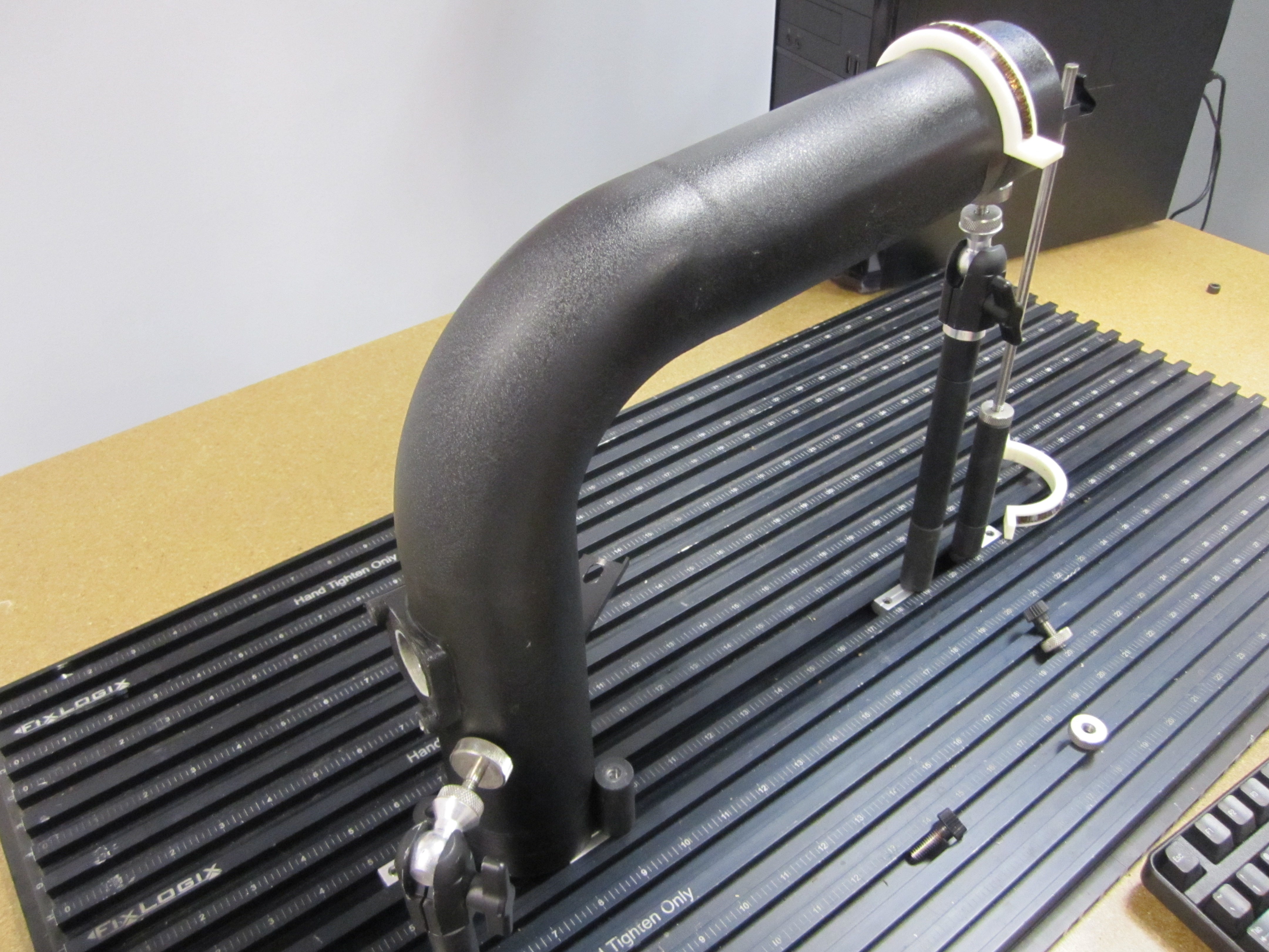
Our first target was the AFR issues. Our engineers noted that the factory intake design used an air straightener in the piping prior to the MAF. This device is used to greatly improve MAF readings by smoothing the airflow across the sensor, which would create a more accurate and consistent reading. A second adjustment to the design includes alteration of the cross-sectional area of the MAF housing. After a few selected sizes were tested we settled on one that provided exceptional power gains while maintaining a safe AFR. After solidifying this design, a final prototype was constructed utilizing our high-flow filter, fabricated aluminum piping, Mishimoto air straightener, and MAF housing.
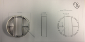
Mishimoto air straightener
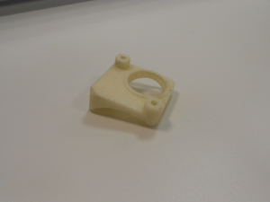
3D Printed MAF housing

CMM of intake pipe
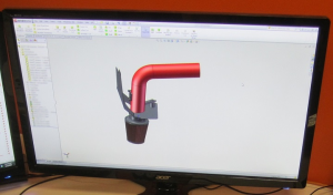
Solidworks Rendering
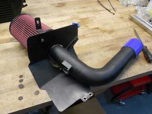
Prototype shroud designed
Next, we will work to further test and improve this design. Swing by for the next installment, where we will be conducting further dyno tests including a few videos!
