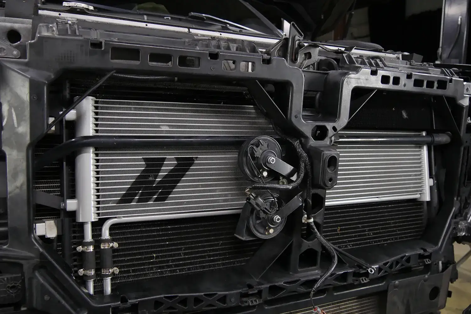
Cool Your Charge! The 2015 WRX Front-Mount Intercooler Build, Part 3: Pipe Routing and Fabrication
Interested in picking up our 2015 WRX FMIC kit? Check out more details on our product page linked below!
Mishimoto Subaru WRX Front-Mount Intercooler Kit

Front-mount intercooler installed
In the last portion of this series we completed the fabrication of our prototype intercooler core and tanks, as well as our new bumper beam. We now had everything in place to construct a piping kit that would route air from the turbocharger to the intercooler and back to the engine.
Hot-Side Piping
We started our piping with the hot-side of the intercooler system. The stock compressor housing uses a two-bolt flange connection, similar to what you would see on a 2008-2014 WRX. As you probably know, the FA20 turbocharger is on the lower front area of the engine, essentially right below the drive belt system. Because of this, our piping for the hot-side would be significantly shorter compared to the traditional turbo location featured on the EJ engine.
We started by 3D printing the flange that connects to the compressor housing. We could then work our piping from here to the cooler.

3D-printed flange for compressor housing
We then worked off the flange to route our piping around the core support to the end tank of the cooler.

Hot-side intercooler piping fabrication
Initially we cut our pieces and temporarily secured them into position for mockup purposes.
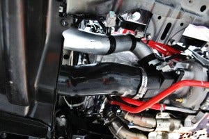
Hot-side intercooler piping fabrication
This pipe was then fully welded.

Hot-side intercooler piping fabrication
On the stock hot-side charge pipe there is a connection point for the BPV. This would need to be considered with the design of our piping. We will be relocating the BPV slightly and will include all necessary components to do so. This kit will function with the stock unit, or any BPV/BOV that is similar in style to the stock piece. Check out the mockup of one of the silicone pieces that moves the BPV to a better position for fitment.

BPV relocation hose
This unit will be a one-piece silicone component with a molded CNC-machined fitting that will function with the stock BPV and turbocharger inlet tube. By designing and including these components, we are creating an entirely direct-fit kit that will require no modification or additional purchases for this install.
Cold-Side Piping
Now that we have sorted out airflow moving to the intercooler, it's time to cover the post-intercooler section. This pipe would be slightly longer and would follow a path similar to the previous generation FMIC piping. We started at the throttle body by wrapping the pipe around the intake manifold toward the front of the vehicle.

Cold-side intercooler pipe fabrication
The cold-side pipe would be made in two pieces for easy installation. After the upper half was in place, we starting routing this pipe around the windshield reservoir and battery, through the core support, and out of the engine bay.
Once through the core support, our engineers fabricated the remaining piping. Fitment is quite tight in this area, requiring extreme precision and a few tests of trial and error. The result was a nice-looking second portion of this cold-side piping.

Cold-side intercooler pipe fabrication
That wraps up our piping for this kit! Check out a shot of the fully welded pipes that we will be using for dyno testing.

Prototype intercooler piping
The Finished Kit!
In just three articles we've started and finished a full front-mount intercooler prototype. Hours of labor, measuring, evaluating, fabrication, and discussions have produced the fully completed prototype you see below!

Full prototype front-mount intercooler kit installed

Full prototype front-mount intercooler kit installed
Our kit fits perfectly with the stock bumper and will not require any cutting or trimming of your brand new WRX!
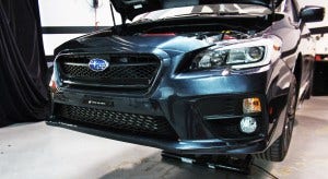
Prototype front-mount intercooler kit installed with bumper
Next time we will be fitting our sensors and making some dyno pulls to gather some data on the performance of this core on the 2015 model! Check back with us next week for some dyno shots, videos, and plots from the runs. We will leave you with a teaser shot!

Preparing for dyno pulls
Thanks
